1. Defining Sheet Metal
Sheet metal is a flat, thin rolled metal product with a uniform thickness, typically ranging between 0.5 and 6 mm. This is the key benchmark. Material below this range is generally classified as foil (e.g., aluminum foil), while thicker sections are considered plate. Note that different sources may cite slightly varying thresholds.
Although this guide focuses primarily on sheet metal processes, given the flexible nature of the term “sheet metal fabrication,” we also cover certain methods commonly applied to thicker plates.

2. Understanding Gauge vs. Millimetres
In addition to metric units, material thickness in the US system is often measured in inches or gauge numbers. However, gauge numbers can be misleading because the same gauge corresponds to different actual thicknesses depending on the material.
Always specify sheet thickness in millimetres or inches rather than gauge. For example, 10-gauge aluminum is about 2.6 mm thick, while 10-gauge steel is roughly 3.5 mm thick. Specifying exact units prevents confusion and potential errors during manufacturing. For conversions, refer to a reliable sheet metal gauge chart.
3. Why Sheet Metal Matters in Industry
Sheet metal fabrication is vital to industry because of its versatility and cost-effectiveness. First, sheet metal can be cut, bent, stretched, deep-drawn, joined, and finished to produce everything from automotive body panels to simple conveyor side plates. Second, the available material properties are remarkably diverse—some inherent to the metal itself (e.g., steel vs. copper vs. aluminium), others achieved through heat treatment.
4. Raw Material Forms: Sheets vs. Coils
Sheet metal is supplied in two primary forms: coils and sheets.
- Coils are used for high‑speed, continuous manufacturing processes such as stamping and roll forming, which require long, continuous strips.
- Sheets are more suitable for most other fabrication operations, including single‑piece or small‑batch cutting, bending, and punching.
Sheets typically come in standard dimensions; 1500 × 3000 mm is one of the most common. Considering these standard sizes during the design phase is critical for optimising material utilisation and controlling costs.
Failure to account for standard sheet dimensions can significantly increase project costs. Poor planning may lead to excessive scrap, premium pricing for non‑standard custom sizes, or unnecessary welding later on.
5. Sheet Metal Cutting Processes
Once the material is selected, the first manufacturing step is almost always laser cutting. The choice of cutting method is a strategic decision based on several key factors:
- Material compatibility
- Material thickness
- Required speed and throughput
- Desired quality and edge finish
- Tolerances
- Part geometry
- Per‑part cost
5.1 CNC Fibre Laser Cutting
How it works
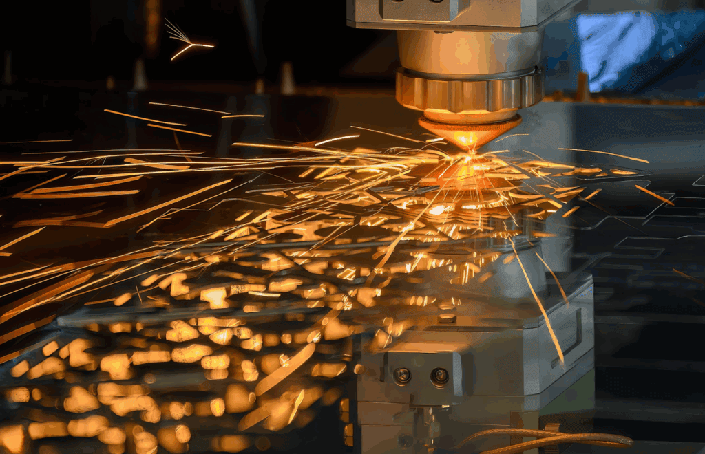
A laser cutting machine produces a high‑intensity beam focused to a tiny spot (typically about 0.2 mm in diameter). This concentrated energy melts the material, while a high‑pressure assist gas (oxygen, nitrogen, or compressed air) blows the molten metal out of the kerf, preventing re‑solidification and ensuring a clean edge.
Three main laser types:
- CO₂ lasers – The most mature technology, operating at 10.6 µm wavelength. Versatile, they can cut non‑metals like wood and plastics as well as metals up to 30 mm thick in steel. However, they struggle with highly reflective metals (aluminium and brass limited to ~10 mm; copper to 4‑5 mm). They require regular maintenance (mirrors, resonator tubes) and consume more power than newer technologies.
- Fibre lasers – Solid‑state technology at 1.07 µm wavelength. This wavelength is more readily absorbed by reflective metals (aluminium, copper, brass), making fibre lasers highly effective for these materials. For thin sheet metal, they are 2‑3 times faster than CO₂ lasers and significantly more energy‑efficient. They have minimal maintenance needs (no mirror alignment). The main limitation is lower maximum cutting thickness in steel (typically 20‑25 mm) compared to high‑power CO₂ lasers.
- Nd:YAG lasers – Another solid‑state type with excellent beam quality and pulse control, ideal for high‑precision applications or foil cutting. However, output power is generally lower, and operating/maintenance costs (due to lamp or diode failures) are higher, so they are reserved for specific niche uses.
Pros and cons of laser cutting
| Advantages | Disadvantages |
|---|---|
| High precision: positional accuracy typically ±0.1 mm | Heat‑affected zone (HAZ) can alter material properties locally (though narrow, 0.1‑0.5 mm) |
| Excellent edge quality: clean, sharp edges with minimal burrs | Thickness limitations: less effective above ~25‑30 mm compared to other thermal methods |
| High speed: especially for thin to medium thicknesses | Reflective materials challenge CO₂ lasers |
| Low distortion: narrow HAZ and high speed allow tight nesting | Warping risk: thin sheets (<1 mm) may distort if heat input is not well controlled |
| Versatility: CO₂ lasers can cut many materials including non‑metals | Fumes and ventilation: hazardous smoke requires robust extraction |
Material considerations
Ideal cutting range is roughly 0.5‑25 mm. While high‑power industrial lasers can cut thicker stock, speed drops and kerf quality deteriorates. Thin sheets (<1 mm) demand precise parameter control to avoid thermal distortion. Overall, laser cutting excels for complex shapes, tight tolerances, and clean edges with minimal post‑processing.
Common applications
- Automotive: precision brackets, exhaust components, prototypes
- Aerospace: lightweight structural parts, engine components
- Electronics: enclosures, chassis, heat sinks, EMI shields
- Architecture: decorative panels, HVAC components, custom metalwork
5.2 Plasma Cutting
Plasma cutting is a thermal process widely used in heavy fabrication and construction. While less precise than laser, it excels at rapidly cutting thick, conductive metals.
How it works
Plasma cutting uses a high‑velocity stream of ionised gas (plasma) to melt and blow material from the kerf. An arc is struck through a compressed gas (nitrogen, argon, or air), ionising it and heating it to extreme temperatures—often exceeding 20,000°C. The electrode and nozzle in the torch generate the arc. Because the plasma is electrically conductive, it sustains the arc between torch and workpiece. This principle limits plasma to conductive materials. With appropriate systems, it can cut thicknesses exceeding 100 mm.
Modern systems use a “pilot arc” (a small plasma spark) to initiate the main cutting arc upon contact with the workpiece.
Pros and cons of plasma cutting
| Advantages | Disadvantages |
|---|---|
| Fast cutting speeds, especially on thick materials | Wider kerf: lower precision than laser |
| Can cut very thick materials: steel >100 mm; aluminium/stainless slightly less | Larger HAZ: more material alteration |
| Cost‑effective for thick plates (>10 mm) often cheaper than laser | Edge quality: may produce dross and slight bevel, often requiring post‑processing |
| Cuts all conductive metals, including reflective ones | Conductive materials only – cannot cut wood or plastics |
| Portable units available for field work | Significant fumes and arc glare; ventilation required |
Material considerations
Plasma works on all conductive metals. Carbon steel can be cut with compressed air or oxygen. Stainless steel and aluminium benefit from nitrogen or argon/hydrogen mixtures (reduced oxidation, better edge quality).
While laser is increasingly competitive up to 25‑30 mm, plasma’s true “sweet spot” is 10‑50 mm. On thin sheets, high heat input may cause warping. Above 50 mm, edges show noticeable bevel and roughness. Thus, plasma is preferred for structural applications where function and strength outweigh cosmetic finish.
Common applications
- Heavy construction: structural steel fabrication, plate cutting
- Shipbuilding: hull plates, structural members
- Industrial equipment: pressure vessels, tanks
- Automotive: heavy‑truck parts, chassis components
- General fabrication: brackets, frames, thick‑plate parts
5.3 Flame Cutting (Oxy‑Fuel Cutting)
Flame cutting, also called oxy‑fuel cutting, is a thermal process specifically for cutting very thick carbon steel plates. Not a first choice for thin sheet metal, it is valued for its economy and portability, especially on‑site or in heavy‑steel workshops.
How it works
Oxy‑fuel cutting uses a high‑temperature flame from fuel gas (acetylene, propane, or natural gas) to heat low‑carbon steel to its kindling point—about 900°C. Once at that temperature, a separate high‑pressure pure oxygen jet is directed onto the spot, triggering a rapid oxidation reaction (essentially a controlled, high‑speed rusting or burning) that severs the material. The preheat flame and oxygen jet move together along the cut path.
The process is limited to carbon and low‑alloy steels. It works best on mild steel (<0.25% carbon); higher carbon (>0.6%) interferes with the reaction and requires preheating. It does not work on stainless steel, aluminium, or other non‑ferrous metals. Elements like chromium or nickel form protective oxides that resist oxidation, preventing cutting.
Pros and cons of flame cutting
| Advantages | Disadvantages |
|---|---|
| Unmatched thickness capability: excels from 10‑150 mm up to 300 mm+ | Carbon steel only – not for stainless, aluminium, or non‑ferrous |
| Low equipment cost: torches and gas handling are relatively inexpensive | Wide kerf (3 mm+): low precision and material loss |
| Portable: common handheld equipment, ideal for field work | Large HAZ: significantly alters material properties near the cut |
| No electricity needed: runs on fuel gas and oxygen | Poor edge quality: rough, tapered edges with heavy dross; extensive post‑processing required |
| Tool versatility: same torch setup can be used for welding or preheating | Slow cutting speed compared to plasma for same thickness |
Material considerations
Most effective on mild steel (<0.25% C). Higher carbon steels can be cut but require careful preheating and controlled cooling to prevent cracking and embrittlement. The main advantage is handling thicknesses >25 mm where other methods become less economical or slower. Quality is relatively poor, making it unsuitable for precision parts or thin‑gauge sheet.
Common applications
- Construction: cutting structural steel beams and thick plates
- Heavy equipment: manufacturing chassis components, thick brackets
- Demolition and scrap: splitting large metal structures
- Bridge building: on‑site cutting and fitting of structural steel
5.4 Waterjet Cutting
Waterjet cutting is a mechanical erosion process using a high‑speed stream of water. Unlike thermal methods (laser, plasma), it produces no HAZ. Combined with its ability to cut virtually any material, it is indispensable for certain applications.
How it works
Waterjet systems operate in two modes: pure water and abrasive.
- Pure waterjet uses water pressurised up to 210‑620 MPa, focused through a tiny nozzle orifice (~0.2 mm), for cutting soft materials like foam and rubber.
- Abrasive waterjet (the method used for sheet metal) introduces abrasive particles (most commonly garnet) into the high‑pressure stream. The mixture erodes material by high‑speed impact. This is a mechanical cutting method—no melting or chemical reaction. The cutting head, controlled by G‑code, continuously traverses the material, eroding it away, achieving high precision without thermal distortion.
Pros and cons of waterjet cutting
| Advantages | Disadvantages |
|---|---|
| No HAZ: cold process – no distortion or metallurgical changes | Slow cutting speed, especially on thick materials |
| Cuts any material: metals, composites, ceramics, stone, glass | High operating cost: abrasive consumption and pump maintenance |
| Excellent edge quality: smooth, satin‑like finish, often no post‑processing | Taper risk: slight edge taper on very thick materials (compensated by 5‑axis heads) |
| Can cut thick materials: up to 250 mm in metal | Very noisy |
| High precision: tolerances depend on cutting speed |
Material considerations
Waterjet is ideal for materials that are difficult or impossible to cut thermally—tool steels, titanium, special alloys, and composites. It is the preferred choice for heat‑sensitive materials (e.g., heat‑treated parts, alloys that must retain temper) or when design requirements prohibit thermal distortion or property changes. Cut quality is outstanding, especially at slower feed rates, which also yield excellent edge verticality.
Common applications
- Aerospace: titanium components, composite parts, high‑precision brackets
- Medical devices: surgical instruments, implants, precision components
- Tool and die: hardened tool steels, complex die components
- General manufacturing: low‑volume, high‑precision parts from diverse or difficult‑to‑machine materials
5.5 Cutting Process Comparison
| Parameter | Laser | Plasma | Flame | Waterjet |
|---|---|---|---|---|
| Process type | Thermal (melting) | Thermal (plasma arc) | Thermal (oxidation) | Mechanical (erosion) |
| Precision | ±0.1 mm | ±0.2 mm | ±1‑3 mm | ±0.05‑0.1 mm |
| Max thickness (steel) | 25‑30 mm | 100+ mm | 300+ mm | 250+ mm |
| Max thickness (aluminium) | 20‑25 mm | 100+ mm | Not possible | 250+ mm |
| Max thickness (stainless) | 15‑20 mm | 50‑80 mm | Not possible | 200+ mm |
| HAZ width | 0.1‑0.5 mm | 1‑3 mm | 3‑8 mm | None |
| Kerf width | 0.1‑0.5 mm | 1‑8 mm | 3‑10 mm | 0.8‑1.5 mm |
| Cutting speed | Fast (thin) | Very fast (thick) | Slow | Very slow |
| Edge quality | Excellent | Fair to good | Poor | Excellent |
| Suitable materials | Most metals, some non‑metals | Conductive only | Carbon steel only | All materials |
| Operating cost | Medium‑high | Low‑medium | Very low | Very high |
| Equipment cost | High | Medium | Very low | High |
| Best application | Complex shapes, high precision | Thick structural steel | Ultra‑thick carbon steel | High precision, no HAZ |
5.6 Shearing
Shearing is a mechanical cutting process using two opposing blades to cut metal sheet in a straight line. Due to its simplicity and high speed, it is often the most economical method for straight cuts.
How it works
Shearing resembles using scissors. The machine uses upper and lower blades set at a slight angle (1‑2°). This angle, or “shear angle,” means the cut progresses progressively along the length rather than all at once, significantly reducing required force. A clamping mechanism holds the sheet, and a back gauge sets the dimension for precise repeat cuts. Most modern shears are hydraulic, providing smooth motion and high power for thick materials (e.g., up to 25 mm carbon steel).
Parallel‑blade shears, though less common, are excellent for thin sheets and small cuts, producing burr‑free edges unlike angled blades that can deform soft materials. Mechanical shears, less popular but still in some shops, suit thin sheets and are easier to maintain but have limited force at low output.
Pros and cons of shearing
| Advantages | Disadvantages |
|---|---|
| High speed: one stroke cuts a long edge | Straight cuts only – no curves or complex geometry |
| Low operating cost: fast cycle, few consumables (no gases, abrasives) | Edge quality varies: may leave burrs or slight deformation if setup is poor |
| No HAZ: mechanical process – no thermal distortion | Blade wear: blades dull over time, affecting quality and requiring maintenance |
| Simple and reliable: no highly skilled operator needed | Best for ductile materials; hard/brittle metals may fracture poorly |
| High throughput: ideal for high‑volume blanking and preparing blanks |
Material considerations
Shearing works best on ductile materials—mild steel, medium‑carbon steel, stainless steel, and aluminium. Harder materials require more force and accelerate blade wear. Cut edges typically have a small burr on the bottom. Quality is heavily influenced by blade clearance (the gap between upper and lower blades), typically set at 5‑10% of material thickness. Too small a clearance accelerates wear; too large causes bending/distortion and heavy burrs.
Common applications
- Stock material suppliers: cutting large plates into smaller saleable sizes
- HVAC: preparing straight sections of galvanised steel for ductwork
- Roofing: cutting metal roofing and wall panels
- General fabrication: preparing blanks for subsequent bending or punching
- Appliance manufacturing: creating flat blanks for deep‑drawing processes
5.7 Blanking and Punching
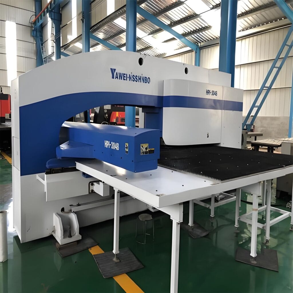
Blanking and punching are high‑speed mechanical cutting processes ideal for large‑volume production. Using specialised die and punch sets, they achieve extremely fast cycle times, consistent quality, and high dimensional repeatability.
How they work
Both processes involve a punch (upper tool) forcing the sheet into a die opening (lower tool). The key difference is intent—which piece becomes the product:
- Blanking: The punched‑out piece is the desired product; the surrounding “skeleton” is scrap. Used for washers, gaskets, gear blanks, etc.
- Punching: The punched‑out piece is scrap; the main sheet with holes or slots is the product. Used for vents in electronics enclosures or mounting holes in brackets.
- Fine blanking: A high‑precision variant using extremely tight clearances and controlled pressure to produce smooth, vertical edges—common for surgical instruments or watch parts.
- Perforating: A form of punching using multiple punches in one stroke to create many holes in a set pattern, often for decorative or functional screens.
Modern manufacturing often combines punching and bending to create complex parts with high repeatability in volume production.
Pros and cons of blanking/punching
| Advantages | Disadvantages |
|---|---|
| High speed: cycle times extremely fast; some presses reach 1000 strokes/min | High tooling cost: custom dies (punch and die) are expensive, especially for complex shapes |
| Excellent repeatability: ideal for high volumes – every part identical | Thickness limitations: best for sheet metal, typically ≤6 mm |
| Low per‑part cost (volume): once tooling is made, unit cost is very low | Tool wear: dies require monitoring and maintenance to maintain edge quality |
| Good edge quality: properly set tools with correct clearance produce clean edges | Part distortion: possible when punching many holes close together |
| Flexibility (turret punch): CNC turret presses offer flexibility with standard tool libraries |
Material considerations
Punching and blanking are best for ductile materials that do not crack under stress. Carbon steel is common up to 6 mm; stainless (which work‑hardens) is typically limited to 3‑4 mm. Aluminium alloys are suitable due to softness, though they may stick to punches.
Edge quality depends on material ductility. Ductile materials yield smoother sheared edges; harder materials show larger fracture zones and rougher surfaces.
To prevent distortion and ensure part quality, follow these design rules:
- Hole diameter: Minimum hole diameter should be at least equal to material thickness (preferably larger).
- Hole spacing: Distance between holes should be at least 1.5× material thickness.
- Edge distance: From hole to part edge should be at least 2.5× thickness to prevent bulging or deformation.
Common applications
- Electronics: chassis vents, connector housings, perforated EMI shields
- Automotive: body panel mounting holes, electrical contacts, precision gears
- Appliances: control panel openings, ventilation grilles, mounting brackets, decorative perforations
- HVAC: duct connectors, filter housings, airflow control components
6. Sheet Metal Forming Processes
After flat blanks are cut, the next step is often forming—any process that applies force exceeding the metal’s yield strength to create a permanent new shape.
6.1 Springback and Compensation
A critical concept in all metal forming is springback—the material’s elastic recovery, tending to “bounce back” toward its original flat shape after forming force is removed. This occurs because bending creates two zones: the outer layer is stretched, the inner layer is compressed. Most materials resist compression more than tension, so when the die retracts, the compressed inner layer pushes the material back slightly. This is especially common in air bending.
To achieve precise final angles, several compensation methods are used:
- Over‑bending: Bending the part beyond the required angle so it springs back to the target.
- Bottom bending: Using greater force to press the material into the bottom of the die, causing plastic deformation that minimises springback.
- Punch/die selection: Using a smaller punch radius also helps “set” the bend, reducing springback.
Springback means that the final angle is highly dependent on material properties, thickness, and bend radius. Designers must also consider bend sequence, as some flanges may obstruct the press brake tooling, making subsequent bends impossible.
6.2 Bending (Press Brake)
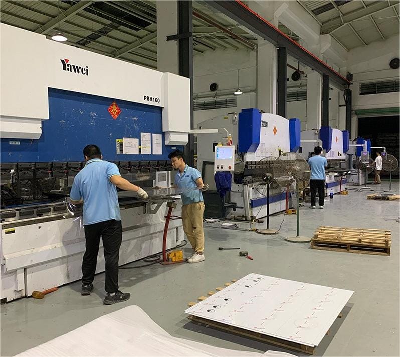
When engineers speak of bending, they almost always mean press brake bending. This is the most common sheet metal forming process, capable of producing everything from simple 90° bends to complex multi‑bend geometries.
How it works
A press brake uses a punch to force sheet metal into a V‑shaped die. There are three primary methods:
- Air bending – The most common and flexible. The punch pushes the material into the V‑die but not to the bottom. The final angle is determined by punch penetration depth, allowing one die to create various angles. Compensation for springback is required.
- Bottom bending – The punch presses the material fully against the die walls and bottom. This uses greater force, helps “set” the angle, and significantly reduces springback. The angle is determined by the die; less flexible than air bending.
- Coining – Uses extreme force, pressing the punch into the material and thinning it at the bend point. This results in full plastic deformation and virtually no springback, offering high precision but faster tool wear.
Pros and cons of bending
| Advantages | Disadvantages |
|---|---|
| High flexibility: one machine can produce simple and complex geometries | Springback requires careful compensation and process control |
| Cost‑effective tooling: dies are relatively standard; suits prototyping and high volume | Minimum bend radius limited by thickness and ductility |
| Widely available: press brakes are standard in nearly every sheet metal shop | Tool marks: punches and dies may leave visible “imprints” on the part surface |
| Strong parts: solid, rigid corners from single piece of material | Grain direction: bending parallel to grain may cause cracking, especially at small radii |
Material considerations
Minimum bend radius rule: Too small a radius is a common cause of cracking.
- Carbon steel and ductile aluminium alloys: recommended minimum inside radius = 1× thickness.
- Harder aluminium alloys: more prone to cracking, require larger radii (2‑3× thickness).
- Stainless steel: work‑hardens rapidly, requires ~2× thickness.
6.3 Deep Drawing
Deep drawing is a forming process that pushes a flat blank through a die opening, stretching and compressing it into the shape of a punch. It produces seamless parts with significant depth—cups, boxes, or housings. Shallow drawing is a similar operation with less depth.
How it works
- A flat, pre‑cut blank is placed over the die cavity.
- A blank holder (pressure pad) descends, clamping the blank firmly against the die face.
- The punch descends, pushing the centre of the blank into the die.
- The blank holder maintains pressure, allowing material to flow radially inward while preventing wrinkling.
- The material is stretched and formed to the precise geometry of punch and die.
Pros and cons of deep drawing
| Advantages | Disadvantages |
|---|---|
| Produces seamless, strong parts – ideal for liquid/gas‑tight containers; continuous grain structure | Very high tooling cost: custom punch, die, and blank holder are complex and expensive |
| High‑volume production: once set up, fast and repeatable | Material limitations: requires highly ductile/formable materials that can stretch without fracture |
| Complex geometries possible with progressive drawing | Failure risks: prone to cracking, wrinkling, or “earing” if parameters are not perfect |
Material considerations
Deep drawing is only suitable for metals that can significantly stretch and flow without fracture—mild steel, many aluminium alloys, and stainless steels. Success depends heavily on material quality and preparation:
- Uniform thickness: Blanks must have consistent thickness to prevent thin spots that may tear.
- Burr‑free blanks: Cleanly sheared blanks are essential; burrs act as stress raisers initiating cracks.
- Lubrication: Proper friction control via lubricants is vital to prevent sticking to dies and excessive heat generation.
Deeper parts (e.g., metal cups) may require multiple drawing stages with intermediate annealing to restore ductility.
Common applications
- Automotive: oil pans, fuel tanks, door panels, structural body parts
- Kitchen appliances: stainless steel sinks, cookware, range hoods
- Packaging: aluminium cans, food containers, aerosol cans, metal lids
- Electronics: enclosures, heat sink housings, battery cases

6.4 Roll Bending (Plate Rolling)
Roll bending uses a series of rotating rolls to curve sheet metal into cylindrical or conical shapes. It is used for consistent large‑radius curves that are impractical with a press brake, with no length limitations.
How it works
The most common configuration is the three‑roll plate roll, with two lower support rolls and one adjustable top roll that applies pressure to determine the bend radius. Four‑roll machines add a fourth roll to pre‑bend the leading and trailing edges, eliminating the “flat spots” typical of three‑roll systems. Powered rolls also feed the material through. Proper sheet alignment is essential for straight, consistent cylinders. Depending on the target radius, multiple passes may be needed to achieve the final geometry gradually.
Pros and cons of roll bending
| Advantages | Disadvantages |
|---|---|
| Large, consistent radii – smooth curves impossible with single‑hit press bending | Minimum radius limited by roll diameter and material thickness |
| No length limitation – can form continuous curved sections like pipes or long tank segments | Multiple passes required for precise radii – time‑consuming |
| Shape versatility – can form conical and variable‑radius shapes | Flat spots: three‑roll machines tend to leave small flat sections at start and end |
| Suited for thick materials – excellent for plates and structural shapes | Limited to simple curved profiles |
Material considerations
Roll bending works for most ductile sheet metals. The gradual, large‑radius forming significantly reduces cracking risk compared to sharp press‑brake bends. The minimum bend radius is typically 3‑5× thickness, making roll bending ideal for large‑curvature work. While “step bending” on a press brake can simulate large curves, it does not produce a true smooth radius like roll bending.
Roll bending excels with thicknesses above 6 mm. For these thicker plates, it is far more efficient than other methods for large‑diameter cylinders, tanks, and structural curves. Springback is minimal due to the progressive stress distribution, though soft materials like aluminium may be prone to roll marking.
7. Assembly
Once parts are cut and formed, they usually need to be joined into subassemblies or finished products. The choice of joining method affects strength, appearance, cost, and serviceability. Each offers different trade‑offs.
7.1 Welding
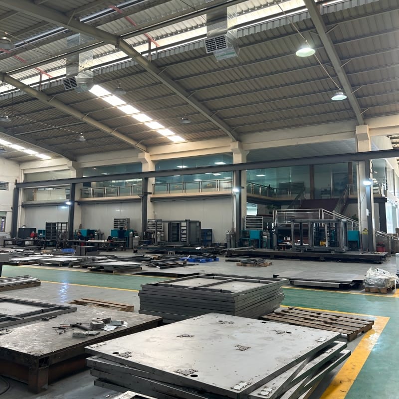
Welding creates permanent, high‑strength joints by melting and fusing the base materials, often with filler. It produces the strongest joints, ranging from precise manual arc welding to high‑speed automated resistance welding.
Arc welding processes
Arc welding uses an electric arc to generate intense heat, melting the base and filler materials. Shielding gas protects the molten weld pool from atmospheric contamination.
- TIG (Tungsten Inert Gas) – Uses a non‑consumable tungsten electrode and inert gas shielding. Excellent heat control and weld quality, ideal for thin materials and clean, precise welds. Manual, high‑strength, flexible, but relatively slow.
- MIG (Metal Inert Gas) – Uses a consumable wire electrode fed continuously through a gun that also supplies shielding gas. Good balance of speed and quality; easier to learn than TIG; suitable for carbon steel, stainless, and aluminium.
- Stick welding (SMAW) – Uses a consumable electrode with a flux coating that generates its own shielding gas when burned. Simple, portable, low‑cost, ideal for outdoor work, but weld quality is lower than TIG or MIG.
Resistance welding processes
- Spot welding – Joins overlapping sheets without filler. Current passes through the sheets under pressure, creating a small localised fusion point. High‑speed, automated, dominant in automotive body assembly.
- Seam welding – Uses rotating wheel electrodes to produce a series of overlapping spots, forming a continuous leak‑tight seam. Common for fuel tanks, containers, and HVAC ducts.
Pros and cons of welding
| Advantages | Disadvantages |
|---|---|
| Highest strength: continuous fused joint, often matches base material | HAZ: intense heat alters material properties around the weld |
| Joins different thicknesses: effectively connects thick to thin | High skill requirement: quality (especially TIG) depends heavily on operator skill |
| Rigidity: excellent load transfer and stiffness | Permanent: cannot be disassembled for maintenance without cutting |
| Leak‑tight: TIG and seam welding can create sealed joints | Distortion: high heat input can warp thin sheets |
Material considerations
Most common metals can be welded, but techniques and fillers must be carefully chosen.
- Carbon steel has excellent weldability.
- Stainless steel requires careful heat control to prevent carbide precipitation (which reduces corrosion resistance).
- Aluminium is more difficult due to its oxide layer and high thermal conductivity; requires clean surfaces and proper shielding.
A major limitation: surface coatings must be removed before welding. Painted, powder‑coated, or galvanised parts must be ground clean at the joint. This often adds production complexity, requiring parts to move from fab shop to welding cell and then to third‑party coating.
7.2 Brazing and Soldering
Brazing and soldering resemble welding but with a key difference: they use filler metal to form a joint without melting the base material. This lower‑temperature approach avoids many welding‑related issues.
How they work
Both rely on capillary action to draw molten filler into the tiny gap between two closely fitted parts. The filler bonds to the surfaces and solidifies
- Brazing uses filler with a melting point above 450°C (common fillers: silver alloys, copper‑phosphorus).
- Soldering uses filler with a melting point below 450°C (common: tin‑lead or lead‑free alloys).
Pros and cons of brazing/soldering
| Advantages | Disadvantages |
|---|---|
| Low heat input: reduces distortion, no large HAZ, preserves base properties | Lower strength: joint strength limited by filler, not base material |
| Joins dissimilar metals: excellent for materials difficult to weld together | Requires precise temperature control to melt filler without melting base |
| Clean appearance: neat joints with little post‑processing | Flux removal necessary: flux used to clean surfaces must be thoroughly removed to prevent corrosion |
Material considerations
Commonly used on copper, brass, and many steels. Aluminium and stainless can be joined but require specific fluxes and filler alloys to handle their protective oxides. Soldering is typically for thinner sheets; brazing can handle parts up to ~6 mm. Joint design is critical: for proper capillary action, the gap between mating parts must be very small and consistent—typically 0.05‑0.2 mm.
Common applications
- Brazing: HVAC systems (refrigerant lines), heat exchangers, aerospace components requiring leak‑tight joints
- Soldering: electronics assembly (PCBs), light‑duty mechanical connections and plumbing
7.3 Mechanical Fastening
Mechanical fastening is an essential joining alternative to welding. Key advantages: no HAZ, ability to join dissimilar and coated materials, and assembly can be done after surface finishing. Many methods also create detachable joints, facilitating disassembly, maintenance, and repair—a critical requirement in many product designs.
Bolting and screwing
Threaded fasteners (bolts, screws, nuts) create strong, reliable joints, often detachable.
- Machine screws mate with nuts or pre‑tapped holes.
- Self‑tapping screws form their own threads during installation, ideal for creating strong “bite” in thin sheet metal.
When properly tightened, bolted joints hold parts together through compressive friction. This means they are strong in shear because friction prevents sliding, rather than relying on the bolt’s shear strength. The bolt itself is primarily in tension—its strongest direction.
Riveting
Riveting creates permanent joints using deformable fasteners (rivets) inserted through holes and mechanically expanded to form “heads” on both sides.
- Solid rivets are simple and strong but require access from both sides.
- Blind rivets (pop rivets) are popular in sheet metal fabrication because they can be installed from one side.
- Self‑piercing riveting is a high‑speed automated process where the rivet pierces the top sheet and expands in the bottom sheet without pre‑drilling.
Clinching
Clinching is a high‑speed, permanent joining method similar to spot welding and self‑piercing riveting but with one key difference: it uses no consumables. It uses a punch and die to draw and “clinch” two layers of metal together, forming a strong, interlocking mechanical button. Widely used in HVAC and appliance industries.
Pros and cons of mechanical fastening
| Advantages | Disadvantages |
|---|---|
| No heat input: preserves material properties | Stress concentration: loads concentrated at fastener holes – potential fatigue points |
| Joins dissimilar materials: easily connects different metals without galvanic corrosion issues | Holes required: most methods need drilling or punching – extra operation |
| Allows disassembly: bolts and screws create detachable joints for service | Access required: many fasteners need access from both sides |
| Suits coated parts: parts can be painted, powder‑coated, or plated before assembly | Corrosion risk: improper fastener material choice may cause galvanic corrosion |
| Simple operation: many methods do not require highly skilled labour | Added weight: fasteners add weight compared to welding or adhesive bonding |
Material considerations
Mechanical fastening works on virtually all sheet materials. However, fastener material selection is critical when joining dissimilar metals or in corrosive environments—use compatible materials to prevent galvanic corrosion. Processes like clinching and self‑piercing riveting require ductile materials that can deform without cracking.
7.4 Adhesive Bonding
Adhesive bonding uses structural adhesives to create strong, lightweight joints that distribute loads over large areas rather than at discrete points. Modern adhesives can match mechanical fasteners in strength and offer additional benefits like moisture sealing and vibration damping.
How it works
Structural adhesives cure via chemical cross‑linking, forming bonds that hold parts together. The process typically involves three steps:
- Surface preparation – The most critical step. Surfaces must be thoroughly cleaned of oils, grease, and oxides—using solvent wiping, mechanical abrasion, or chemical etching.
- Adhesive application – A thin, controlled layer is applied.
- Curing – The adhesive cures chemically, triggered by time, heat, moisture, or UV light, depending on type.
Pros and cons of adhesive bonding
| Advantages | Disadvantages |
|---|---|
| Even stress distribution: spreads load across bonded area, reduces stress concentrations, improves fatigue resistance | Surface preparation is critical: bond strength highly dependent on meticulous cleaning and pre‑treatment |
| Joins dissimilar materials: excellent for different materials, no galvanic corrosion | Environmental sensitivity: heat, moisture, or chemical exposure may reduce bond strength |
| Seals joints: continuous bond provides moisture and contaminant barrier | Difficult to disassemble: joints are permanent; cannot be separated without damage |
| Aesthetically pleasing: smooth surface with no visible fasteners or weld marks | Quality control challenging: difficult to non‑destructively test bond quality/strength |
| Lightweight: minimal added weight compared to fasteners | Curing time: may take minutes to hours, potentially slowing production |
Material considerations
Structural adhesives can bond all common metals, provided surfaces are properly prepared. Oily or oxidised surfaces will cause bond failure. The success of adhesive bonding is 90% preparation—surfaces must be clean, dry, and contaminant‑free. For structural applications, this typically means abrasion or chemical primers to enable the adhesive to form a strong chemical bond.
8. Post‑Processing: Finishing and Coating
Post‑processing is the final manufacturing stage, divided into two key areas: surface finishing (mechanical removal of imperfections from cutting and forming) and protective coating (applying layers to protect against environmental degradation and ensure service life).
8.1 Surface Finishing
Surface finishing mechanically treats the part surface to remove defects, improve appearance, and prepare for final coatings.
Deburring – The essential operation to remove sharp edges and burrs from cutting, punching, and forming.
- Manual deburring remains common, using files, scrapers, and abrasive tools.
- Tumbling uses abrasive media in rotating drums to uniformly deburr batch parts, providing consistent texture.
- Electrochemical deburring (a reverse of plating) uses electric current and electrolyte to remove material from the workpiece.
Grinding and polishing
- Grinding uses bonded abrasives to remove metal—more aggressive than deburring—for smoothing rough areas or preparing entire surfaces for coating.
- Polishing is a finer process that refines the surface to a smoother, brighter finish. For metals like stainless that do not require coating, polishing can be the final step. It reduces microscopic roughness, inhibiting bacterial growth and making parts easier to sanitise.

8.2 Protective Coatings
Most metals oxidise or corrode when exposed to the environment. Protective coatings ensure structural and functional integrity throughout service life.
Powder coating – A common, highly durable finish. Dry coloured powder is electrostatically charged and sprayed onto earthed metal parts. The parts are then cured in an oven, where the powder melts and flows into a uniform, resilient coating, typically 25‑100 µm thick. It offers excellent impact and abrasion resistance, far superior to most wet paints.
Wet spraying – Modern liquid spraying applies multiple layers: primers for adhesion and corrosion protection, and topcoats for colour, gloss, and environmental resistance.
Galvanising – Applying a protective zinc coating to steel.
- Hot‑dip galvanising: Immersion in molten zinc bath, producing a thick, durable, metallurgically bonded coating. It has a famous “self‑healing” property—if scratched, surrounding zinc corrodes preferentially, sacrificing itself to protect exposed steel.
- Electro‑galvanising: Uses electroplating to deposit a thinner zinc coating, offering a brighter finish and better dimensional control for precision parts.
Anodising – An electrochemical process exclusive to aluminium. It forms a controlled, hard aluminium oxide layer on the surface, providing excellent corrosion resistance without significant thickness increase.
| Type | Method | Key characteristics |
|---|---|---|
| Type I anodising | Chromic acid | Very thin; for minimal dimensional change |
| Type II anodising | Sulphuric acid | Standard thickness; most common, good corrosion resistance, dyeable |
| Type III anodising | Sulphuric acid | Thick and hard; excellent wear resistance |
Plating – Depositing thin metal layers (e.g., nickel, chromium) for decorative or functional purposes. Precise thickness control makes it suitable for precision applications.
9. Choosing the Right Process for Your Design
Understanding the full spectrum of sheet metal fabrication processes is essential for cost‑effective and functional design. From material selection to part geometry, initial decisions directly impact which cutting, forming, and finishing options remain available.
An engineer who considers the entire manufacturing chain—from standard sheet sizes to final protective coatings—is most likely to design parts that are not only functional but also reliable and cost‑effective to produce.
10.Contact Us
Click here: Contact Us
Email: [email protected]
Author:David Wu
URL: https://zhmfr.com
video URL:https://www.youtube.com/@David-OEM
China Kewei Intelligent Technology Co., Ltd
Address:No. 23, Yexing Road, Xiangxi Industrial Zone, Liaobu Town, Dongguan City, Guangdong Province, China
With our profound expertise in customized sheet metal manufacturing services, CNC milling and turning, and metal stamping processing, we meet the complex needs of the automation equipment industry, new energy storage industry, and manufacturing industry. Our service portfolio includes automation equipment enclosures, precision mechanical parts, energy storage cabinet enclosures, and other customized metal products. We use advanced laser cutting, welding, and forming technologies to produce parts with strict tolerances and excellent surface finish. Whether you need small batch prototypes for research and development or large-scale production for assembly lines, our scalable solutions ensure the quality, cost-effectiveness, and on-time delivery of your industrial projects.