Sheet Metal Bending
In metal fabrication, sheet metal bending is one of the most essential forming processes. Whether you work with aluminium, stainless steel, or mild steel, the quality of the bend directly affects the final part’s accuracy and service life. This guide draws on real‑world shop‑floor experience to list the most frequent bending defects, their root causes, and actionable fixes – helping you reduce scrap and improve efficiency.
1. Bending Basics: Key Parameters
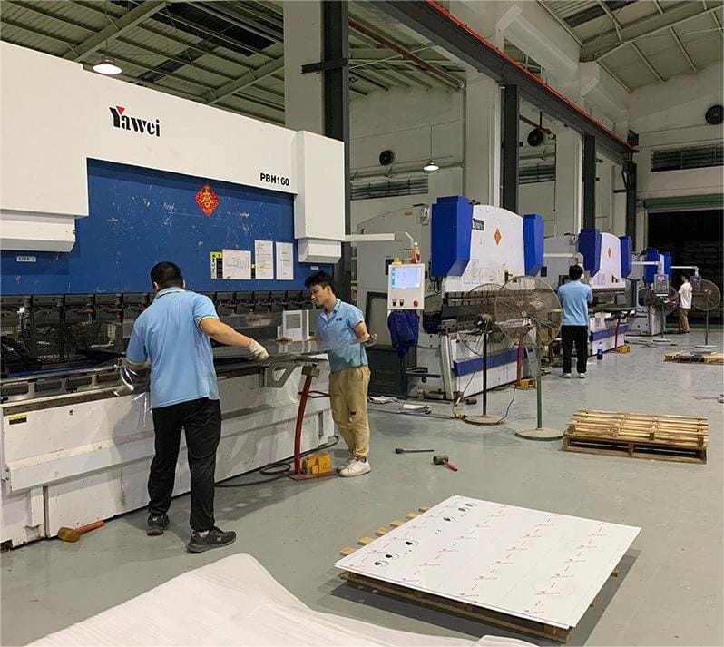
Bending is typically done on a press brake (or bending machine). The operator places the workpiece on the lower die, lifts the clamping plate (hold‑down) via a lever, slides the part into position, lowers the clamp to secure it, then applies force through the bending lever to form the angle.
Critical parameter – the minimum bend radius – depends on the material’s ductility and thickness. For aluminium, the bend radius must be greater than the sheet thickness to avoid cracking. Also, because all metals spring back after bending, the actual bend angle must be slightly over‑bent (typically 1°–3° extra) to compensate. The exact value should be determined by trial bending for each material and thickness.
2. 12 Typical Bending Defects and How to Fix Them
Problem 1: Bent edge is not straight, dimensions vary
Causes
- No scoring line or pre‑bend step in the process design
- Insufficient clamping (hold‑down) force, allowing slip
- Uneven wear on punch/die radii, or unbalanced bending force
- Bend height too small (below the minimum allowed)
Solutions
- Add a scoring line or pre‑bend operation
- Increase clamping pressure
- Regrind the punch and die to ensure even clearance and polished radii
- Make sure the bend height is at least the minimum (typically 2–3× sheet thickness)
Problem 2: Scratches or galling on the outer surface after bending
Causes
- Rough surface on the raw material (burrs, oxide)
- Punch radius too small
- Bending clearance too tight, causing friction
Solutions
- Polish the punch and die surfaces to Ra ≤ 0.8 μm
- Increase the punch radius slightly
- Readjust clearance – recommended at 1.05–1.15 × sheet thickness
Problem 3: Cracks at the bend corner
Causes
- Inside bend radius smaller than the material’s minimum
- Grain direction parallel to the bend line (anisotropy)
- Burr side facing outward, creating a stress concentration
- Material too brittle (e.g., hard‑temper aluminium, high‑carbon steel)
Solutions
- Increase the punch radius so that it is ≥ material thickness
- Change the blanking layout so that the grain direction is at 30°–45° to the bend line
- Place the burr side on the inside of the bend radius
- Anneal hard materials or switch to a softer temper grade
Problem 4: Locating holes become deformed during bending
Cause
When using spring‑loaded bending with hole location, the outer arm stretches due to friction with the die surface, pulling the locating hole out of shape.
Solutions
- Use a V‑die or U‑die forming method instead
- Increase the pressure on the ejector (pads) to reduce slip
- Add knurling or grid patterns on the ejector plate to increase friction and prevent part movement
Problem 5: Localised thinning on the bent surface
Causes
- Die radius too small, restricting material flow
- Clearance between punch and die less than sheet thickness, causing excessive squeezing
Solutions
- Enlarge the die radius (recommended 2–4 × thickness)
- Regrind the die to achieve a clearance of 1.05–1.10 × thickness
Problem 6: Bulging or waviness at the part ends
Cause
During bending, the outer surface is stretched (contraction in width) while the inner surface is compressed (expansion), leading to end‑face distortion and bulging.
Solutions
- Apply sufficient coining pressure (≥25% of the press capacity) at the final stage
- Match the die radius exactly to the desired outside radius of the part
- Add a secondary sizing operation for better flatness
Problem 7: Bottom of a U‑shape is not flat
Causes
- Raw material already has waviness or poor flatness
- Ejector plate has too small contact area or insufficient force
- No ejector mechanism inside the die
Solutions
- Level the sheet before bending (flatness ≤ 0.5 mm/m)
- Enlarge the ejector area and increase its force
- Install ejector pins or nitrogen springs, and add a sizing/coining step
Problem 8: Axial misalignment of two opposing holes after bending
Cause
Springback changes the actual bend angle, causing the centre lines of the two holes to shift relative to each other.
Solutions
- Add a coining or bottoming operation (with negative clearance or compensation features)
- Modify the die design – e.g., add a counter‑radius or compensation block to counteract springback
Problem 9: Hole position accuracy out of tolerance
Causes
- Incorrect blank length calculation (unfolded size)
- Springback alters the angle, shifting hole positions
- Unstable locating (inconsistent feeding)
Solutions
- Calculate the neutral‑line length more accurately (using K‑factor or trial‑and‑error)
- Use angle correction or over‑bending to compensate for springback
- Improve the locating method (e.g., side stops, clamping) or add pilot holes for process positioning
Problem 10: Bend line not parallel to the line connecting two holes
Cause
When the bend height is below the minimum, the bend zone expands outward, distorting the bend line.
Solutions
- Increase the bend height (recommended ≥ 3× thickness) if design allows
- If not, change the process – e.g., punch holes after bending, or use segmented bending
Problem 11: Bow‑shaped distortion in the width direction
Cause
Uneven stretching/compression across the width of the part creates torsion and bowing.
Solutions
- Raise bending pressure (increase by 10–20%)
- Add a sizing operation or side‑clamping during bending
- Keep the grain direction at 30°–60° to the bend line – avoid parallel orientation
Problem 12: Parts with notches sag downward
Cause
The notches allow the two side legs to spread outward, leaving the bottom unsupported and causing a sagging deflection.
Solutions
- Redesign the part to include stiffening ribs or temporary bridges
- Leave process tabs at the notch locations – bend first, then trim the tabs off later (by laser or punching)
Note: Using inferior boards can also lead to bending and cracking. Although their price is relatively favorable, their quality cannot be guaranteed
3. Three Golden Rules for High‑Quality Bending
- Plan ahead – scoring, pre‑bending, grain layout, and blank sizing are more important than any later adjustment.
- Keep your tooling precise – balance clearance, radius, and surface finish to get good form and good surface quality at the same time.
- Always compensate for springback – run trial bends to measure the actual rebound, then apply over‑bending or use corrective die features.
Pro tip: For a quick reference, we recommend keeping a bending parameter chart (material, thickness, punch radius, die opening, and springback compensation) near every press brake.
This guide is brought to you by our experienced sheet metal fabrication team. We regularly share practical know‑how on forming, stamping, welding, and more. Feel free to bookmark this page or share it with your workshop colleagues – and if you have specific questions, just ask!
Contact Us
Click here: Contact Us
Email: [email protected]
Author:David Wu
video URL:https://www.youtube.com/@David-OEM
China Kewei Intelligent Technology Co., Ltd
Address:No. 23, Yexing Road, Xiangxi Industrial Zone, Liaobu Town, Dongguan City, Guangdong Province, China
With our profound expertise in customized sheet metal manufacturing services, CNC milling and turning, and metal stamping processing, we meet the complex needs of the automation equipment industry, new energy storage industry, and manufacturing industry. Our service portfolio includes automation equipment enclosures, precision mechanical parts, energy storage cabinet enclosures, and other customized metal products. We use advanced laser cutting, welding, and forming technologies to produce parts with strict tolerances and excellent surface finish. Whether you need small batch prototypes for research and development or large-scale production for assembly lines, our scalable solutions ensure the quality, cost-effectiveness, and on-time delivery of your industrial projects
相关文章:
 The Complete Guide to Sheet Metal Fabrication: Processes, Materials, and Best Practices
Custom Cut Sheet Metal: A Complete Guide for Buyers and Engineers
The Complete Guide to Sheet Metal Fabrication: Processes, Materials, and Best Practices
Custom Cut Sheet Metal: A Complete Guide for Buyers and Engineers
 Custom Metal Enclosures in China: Your Complete Guide to OEM Sheet Metal Housings
 Differences Between Sheet Metal Parts and Machined Parts: How to Tell Them Apart